8 IP version 6¶
What has been learned from experience with IPv4? First and foremost, more than 32 bits are needed for addresses; the primary motive in developing IPv6 was the specter of running out of IPv4 addresses (something which, at the highest level, has already happened; see the discussion at the end of 1.10 IP - Internet Protocol). Another important issue is that IPv4 requires (or used to require) a modest amount of effort at configuration; IPv6 was supposed to improve this.
By 1990 the IETF was actively interested in proposals to replace IPv4. A working group for the so-called “IP next generation”, or IPng, was created in 1993 to select the new version; RFC 1550 was this group’s formal solicitation of proposals. In July 1994 the IPng directors voted to accept a modified version of the “Simple Internet Protocol Plus”, or SIPP (RFC 1710), as the basis for IPv6. The first IPv6 specifications, released in 1995, were RFC 1883 (now RFC 2460, with updates) for the basic protocol, and RFC 1884 (now RFC 4291, again with updates) for the addressing architecture.
SIPP addresses were originally 64 bits in length, but in the month leading up to adoption as the basis for IPv6 this was increased to 128. 64 bits would probably have been enough, but the problem is less the actual number than the simplicity with which addresses can be allocated; the more bits, the easier this becomes, as sites can be given relatively large address blocks without fear of waste. A secondary consideration in the 64-to-128 leap was the potential to accommodate now-obsolete CLNP addresses (1.15 IETF and OSI), which were up to 160 bits in length, but compressible.
IPv6 has to some extent returned to the idea of a fixed division between network and host portions; for most IPv6 addresses, the first 64 bits is the network prefix (including any subnet portion) and the remaining 64 bits represents the host portion. The rule as spelled out in RFC 2460, in 1998, was that the 64/64 split would apply to all addresses except those beginning with the bits 000; those addresses were then held in reserve in the unlikely event that the 64/64 split ran into problems in the future. This was a change from 1995, when RFC 1884 envisioned 48-bit host portions and 80-bit prefixes.
While the IETF occasionally revisits the issue, at the present time the 64/64 split seems here to stay; for discussion and justification, see 8.10.1 Subnets and /64 and RFC 7421. The 64/64 split is not automatic, however; there is no default prefix length as there was in the Class A/B/C IPv4 scheme. Thus, it is misleading to think of IPv6 as a return to something like IPv4’s classful addressing scheme. Router advertisements must always include the prefix length, and, when assigning IPv6 addresses manually, the /64 prefix length must be specified explicitly; see 8.12.3 Manual address configuration.
High-level routing, however, can, as in IPv4, be done on prefixes of any length (usually that means lengths shorter than /64). Routing can also be done on different prefix lengths at different points of the network.
IPv6 is now twenty years old, and yet usage as of 2015 remains quite modest. However, the shortage in IPv4 addresses has begun to loom ominously; IPv6 adoption rates may rise quickly if IPv4 addresses begin to climb in price.
8.1 The IPv6 Header¶
The IPv6 fixed header is pictured below; at 40 bytes, it is twice the size of the IPv4 header. The fixed header is intended to support only what every packet needs: there is no support for fragmentation, no header checksum, and no option fields. However, the concept of extension headers has been introduced to support some of these as options; some IPv6 extension headers are described in 8.5 IPv6 Extension Headers. Whatever header comes next is identified by the Next Header field, much like the IPv4 Protocol field. Some other fixed-header fields have also been renamed from their IPv4 analogues: the IPv4 TTL is now the IPv6 Hop_Limit (still decremented by each router with the packet discarded when it reaches 0), and the IPv4 DS field has become the IPv6 Traffic Class.

The Flow Label is new. RFC 2460 states that it
may be used by a source to label sequences of packets for which it requests special handling by the IPv6 routers, such as non-default quality of service or “real-time” service.
Senders not actually taking advantage of any quality-of-service options are supposed to set the Flow Label to zero.
When used, the Flow Label represents a sender-computed hash of the source and destination addresses, and perhaps the traffic class. Routers can use this field as a way to look up quickly any priority or reservation state for the packet. All packets belonging to the same flow should have the same Routing Extension header, 8.5.3 Routing Header. The Flow Label will in general not include any information about the source and destination port numbers, except that only some of the connections between a pair of hosts may make use of this field.
A flow, as the term is used here, is one-way; the return traffic belongs to a different flow. Historically, the term “flow” has also been used at various other scales: a single bidirectional TCP connection, multiple related TCP connections, or even all traffic from a particular subnet (eg the “computer-lab flow”).
8.2 IPv6 Addresses¶
IPv6 addresses are written in eight groups of four hex digits, with a-f preferred over A-F (RFC 5952). The groups are separated by colons, and have leading 0’s removed, eg
fedc:13:1654:310:fedc:bc37:61:3210
If an address contains a long run of 0’s – for example, if the IPv6 address had an embedded IPv4 address – then when writing the address the string “::” should be used to represent however many blocks of 0000 as are needed to create an address of the correct length; to avoid ambiguity this can be used only once. Also, embedded IPv4 addresses may continue to use the “.” separator:
::ffff:147.126.65.141
The above is an example of one standard IPv6 format for representing IPv4 addresses (see 8.11 Using IPv6 and IPv4 Together). 48 bits are explicitly displayed; the :: means these are prefixed by 80 0-bits.
The IPv6 loopback address is ::1 (that is, 127 0-bits followed by a 1-bit).
Network address prefixes may be written with the “/” notation, as in IPv4:
12ab:0:0:cd30::/60
RFC 3513 suggested that initial IPv6 unicast-address allocation be initially limited to addresses beginning with the bits 001, that is, the 2000::/3 block (20 in binary is 0010 0000).
Generally speaking, IPv6 addresses consist of a 64-bit network prefix (perhaps including subnet bits) followed by a 64-bit “interface identifier”. See 8.3 Network Prefixes and 8.2.1 Interface identifiers.
IPv6 addresses all have an associated scope, defined in RFC 4007. The scope of a unicast address is either global, meaning it is intended to be globally routable, or link-local, meaning that it will only work with directly connected neighbors (8.2.2 Link-local addresses). The loopback address is considered to have link-local scope. A few more scope levels are available for multicast addresses, eg “site-local” (RFC 4291). The scope of an IPv6 address is implicitly coded within the first 64 bits; addresses in the 2000::/3 block above, for example, have global scope.
Packets with local-scope addresses (eg link-local addresses) for either the destination or the source cannot be routed (the latter because a reply would be impossible).
Although addresses in the “unique local address” category of 8.3 Network Prefixes officially have global scope, in a practical sense they still behave as if they had the now-officially-deprecated “site-local scope”.
8.2.1 Interface identifiers¶
As mentioned earlier, most IPv6 addresses can be divided into a 64-bit network prefix and a 64-bit “host” portion, the latter corresponding to the “host” bits of an IPv4 address. These host-portion bits are known officially as the interface identifier; the change in terminology reflects the understanding that all IP addresses attach to interfaces rather than to hosts.
The original plan for the interface identifier was to derive it in most cases from the LAN address, though the interface identifier can also be set administratively. Given a 48-bit Ethernet address, the interface identifier based on it was to be formed by inserting 0xfffe between the first three bytes and the last three bytes, to get 64 bits in all. The seventh bit of the first byte (the Ethernet “universal/local” flag) was then set to 1. The result of this process is officially known as the Modified EUI-64 Identifier, where EUI stands for Extended Unique Identifier; details can be found in RFC 4291. As an example, for a host with Ethernet address 00:a0:cc:24:b0:e4, the EUI-64 identifier would be 02a0:ccff:fe24:b0e4 (the leading 00 becomes 02 when the seventh bit is turned on). At the time the EUI-64 format was proposed, it was widely expected that Ethernet MAC addresses would eventually become 64 bits in length.
EUI-64 interface identifiers turn out to introduce a major privacy concern: no matter where a (portable) host connects to the Internet – home or work or airport or Internet cafe – such an interface identifier always remains the same, and thus serves as a permanent host fingerprint. As a result, EUI-64 identifiers are now discouraged for personal workstations and mobile devices. (Some fixed-location hosts continue to use EUI-64 interface identifiers, or, alternatively, administratively assigned interface identifiers.)
RFC 7217 proposes an alternative: the interface identifier is a secure hash (22.6 Secure Hashes) of a “Net_Iface” parameter, the 64-bit IPv6 address prefix, and a host-specific secret key (a couple other parameters are also thrown into the mix, but they need not concern us here). The “Net_Iface” parameter can be the interface’s MAC address, but can also be the interface’s “name”, eg eth0. Interface identifiers created this way change from connection point to connection point (because the prefix changes), do not reveal the Ethernet address, and are randomly scattered (because of the key, if nothing else) through the 264-sized interface-identifier space. The last feature makes probing for IPv6 addresses effectively impossible; see exercise 6.0.
Interface identifiers as in the previous paragraph do not change unless the prefix changes, which normally happens only if the host is moved to a new network. In 8.7.2.1 SLAAC privacy we will see that interface identifiers are often changed at regular intervals, for privacy reasons.
Finally, interface identifiers are often centrally assigned, using DHCPv6 (8.7.3 DHCPv6).
Remote probing for IPv6 addresses based on EUI-64 identifiers is much easier than for those based on RFC-7217 identifiers, as the former are not very random. If an attacker can guess the hardware vendor, and thus the first three bytes of the Ethernet address (2.1.3 Ethernet Address Internal Structure), there are only 224 possibilities, down from 264. As the last three bytes are often assigned in serial order, considerable further narrowing of the search space may be possible. While it may amount to security through obscurity, keeping internal global IPv6 addresses hidden is often of practical importance.
Additional discussion of host-scanning in IPv6 networks can be found in RFC 7707 and draft-ietf-opsec-ipv6-host-scanning-06.
8.2.2 Link-local addresses¶
IPv6 defines link-local addresses, with so-called link-local scope, intended to be used only on a single LAN and never routed. These begin with the 64-bit link-local prefix consisting of the ten bits 1111 1110 10 followed by 54 more zero bits; that is, fe80::/64. The remaining 64 bits are the interface identifier for the link interface in question, above. The EUI-64 link-local address of the machine in the previous section with Ethernet address 00:a0:cc:24:b0:e4 is thus fe80::2a0:ccff:fe24:b0e4.
The main applications of link-local addresses are as a “bootstrap” address for global-address autoconfiguration (8.7.2 Stateless Autoconfiguration (SLAAC)), and as an optional permanent address for routers. IPv6 routers often communicate with neighboring routers via their link-local addresses, with the understanding that these do not change when global addresses (or subnet configurations) change (RFC 4861 §6.2.8). If EUI-64 interface identifiers are used then the link-local address does change whenever the Ethernet hardware is replaced. However, if RFC 7217 interface identifiers are used and that mechanism’s “Net_Iface” parameter represents the interface name rather than its physical address, the link-local address can be constant for the life of the host. (When RFC 7217 is used to generate link-local addresses, the “prefix” hash parameter is the link-local prefix fe80::/64.)
A consequence of identifying routers to their neighbors by their link-local addresses is that it is often possible to configure routers so they do not even have global-scope addresses; for forwarding traffic and for exchanging routing-update messages, link-local addresses are sufficient. Similarly, many ordinary hosts forward packets to their default router using the latter’s link-local address. We will return to router addressing in 8.13.2 Setting up a router and 8.13.2.1 A second router.
For non-Ethernet-like interfaces, eg tunnel interfaces, there may be no natural candidate for the interface identifier, in which case a link-local address may be assigned manually, with the low-order 64 bits chosen to be unique for the link in question.
When sending to a link-local address, one must separately supply somewhere the link’s “zone identifier”, often by appending a string containing the interface name to the IPv6 address, eg fe80::f00d:cafe%eth0. See 8.12.1 ping6 and 8.12.2 TCP connections using link-local addresses for examples of such use of link-local addresses.
IPv4 also has true link-local addresses, defined in RFC 3927, though they are rarely used; such addresses are in the 169.254.0.0/16 block (not to be confused with the 192.168.0.0/16 private-address block). Other than these, IPv4 addresses always implicitly identify the link subnet by virtue of the network prefix.
Once the link-local address is created, it must pass the duplicate-address detection test before being used; see 8.7.1 Duplicate Address Detection.
8.2.3 Anycast addresses¶
IPv6 also introduced anycast addresses. An anycast address might be assigned to each of a set of routers (in addition to each router’s own unicast addresses); a packet addressed to this anycast address would be delivered to only one member of this set. Note that this is quite different from multicast addresses; a packet addressed to the latter is delivered to every member of the set.
It is up to the local routing infrastructure to decide which member of the anycast group would receive the packet; normally it would be sent to the “closest” member. This allows hosts to send to any of a set of routers, rather than to their designated individual default router.
Anycast addresses are not marked as such, and a node sending to such an address need not be aware of its anycast status. Addresses are anycast simply because the routers involved have been configured to recognize them as such.
IPv4 anycast exists also, but in a more limited form (10.6.8 BGP and Anycast); generally routers are configured much more indirectly (eg through BGP).
8.3 Network Prefixes¶
We have been assuming that an IPv6 address, at least as seen by a host, is composed of a 64-bit network prefix and a 64-bit interface identifier. As of 2015 this remains a requirement; RFC 4291 (IPv6 Addressing Architecture) states:
For all unicast addresses, except those that start with the binary value 000, Interface IDs are required to be 64 bits long….
This /64 requirement is occasionally revisited by the IETF, but is unlikely to change for mainstream IPv6 traffic. This firm 64/64 split is a departure from IPv4, where the host/subnet division point has depended, since the development of subnets, on local configuration.
Note that while the net/interface (net/host) division point is fixed, routers may still use CIDR (10.1 Classless Internet Domain Routing: CIDR) and may still base forwarding decisions on prefixes shorter than /64.
As of 2015, all allocations for globally routable IPv6 prefixes are part of the 2000::/3 block.
IPv6 also defines a variety of specialized network prefixes, including the link-local prefix and prefixes for anycast and multicast addresses. For example, as we saw earlier, the prefix ::ffff:0:0/96 identifies IPv6 addresses with embedded IPv4 addresses.
The most important class of 64-bit network prefixes, however, are those supplied by a provider or other address-numbering entity, and which represent the first half of globally routable IPv6 addresses. These are the prefixes that will be visible to the outside world.
IPv6 customers will typically be assigned a relatively large block of addresses, eg /48 or /56. The former allows 64−48 = 16 bits for local “subnet” specification within a 64-bit network prefix; the latter allows 8 subnet bits. These subnet bits are – as in IPv4 – supplied through router configuration; see 8.10 IPv6 Subnets. The closest IPv6 analogue to the IPv4 subnet mask is that all network prefixes are supplied to hosts with an associated length, although that length will almost always be 64 bits.
Many sites will have only a single externally visible address block. However, some sites may be multihomed and thus have multiple independent address blocks.
Sites may also have private unique local address prefixes, corresponding to IPv4 private address blocks like 192.168.0.0/16 and 10.0.0.0/8. They are officially called Unique Local Unicast Addresses and are defined in RFC 4193. These replace an earlier site-local address plan (and official site-local scope) formally deprecated in RFC 3879 (though unique-local addresses are sometimes still informally referred to as site-local).
The first 8 bits of a unique-local prefix are 1111 1101 (fd00::/8). The related prefix 1111 1100 (fc00::/8) is reserved for future use; the two together may be consolidated as fc00::/7. The last 16 bits of a 64-bit unique-local prefix represent the subnet ID, and are assigned either administratively or via autoconfiguration. The 40 bits in between, from bit 8 up to bit 48, represent the Global ID. A site is to set the Global ID to a pseudorandom value.
The resultant unique-local prefix is “almost certainly” globally unique (and is considered to have global scope in the sense of 8.2 IPv6 Addresses), although it is not supposed to be routed off a site. Furthermore, a site would generally not admit any packets from the outside world addressed to a destination with the Global ID as prefix. One rationale for choosing unique Global IDs for each site is to accommodate potential later mergers of organizations without the need for renumbering; this has been a chronic problem for sites using private IPv4 address blocks. Another justification is to accommodate VPN connections from other sites. For example, if I use IPv4 block 10.0.0.0/8 at home, and connect using VPN to a site also using 10.0.0.0/8, it is possible that my printer will have the same IPv4 address as their application server.
8.4 IPv6 Multicast¶
IPv6 has moved away from LAN-layer broadcast, instead providing a wide range of LAN-layer multicast groups. (Note that LAN-layer multicast is often straightforward; it is general IP-layer multicast (20.5 Global IP Multicast) that is problematic. See 2.1.2 Ethernet Multicast for the Ethernet implementation.) This switch to multicast is intended to limit broadcast traffic in general, though many switches still propagate LAN multicast traffic everywhere, like broadcast.
An IPv6 multicast address is one beginning with the eight bits 1111 1111 (ff00::/8); numerous specific such addresses, and even classes of addresses, have been defined. For actual delivery, IPv6 multicast addresses correspond to LAN-layer (eg Ethernet) multicast addresses through a well-defined static correspondence; specifically, if x, y, z and w are the last four bytes of the IPv6 multicast address, in hex, then the corresponding Ethernet multicast address is 33:33:x:y:z:w (RFC 2464). A typical IPv6 host will need to join (that is, subscribe to) several Ethernet multicast groups.
The IPv6 multicast address with the broadest scope is all-nodes, with address ff02::1; the corresponding Ethernet multicast address is 33:33:00:00:00:01. This essentially corresponds to IPv4’s LAN broadcast, though the use of LAN multicast here means that non-IPv6 hosts should not see packets sent to this address. Another important IPv6 multicast address is ff02::2, the all-routers address. This is meant to be used to reach all routers, and routers only; ordinary hosts do not subscribe.
Generally speaking, IPv6 nodes on Ethernets send LAN-layer Multicast Listener Discovery (MLD) messages to multicast groups they wish to start using; these messages allow multicast-aware Ethernet switches to optimize forwarding so that only those hosts that have subscribed to the multicast group in question will receive the messages. Otherwise switches are supposed to treat multicast like broadcast; worse, some switches may simply fail to forward multicast packets to destinations that have not explicitly opted to join the group.
8.5 IPv6 Extension Headers¶
In IPv4, the IP header contained a Protocol field to identify the next header; usually UDP or TCP. All IPv4 options were contained in the IP header itself. IPv6 has replaced this with a scheme for allowing an arbitrary chain of supplemental IPv6 headers. The IPv6 Next Header field can indicate that the following header is UDP or TCP, but can also indicate one of several IPv6 options. These optional, or extension, headers include:
- Hop-by-Hop options header
- Destination options header
- Routing header
- Fragment header
- Authentication header
- Mobility header
- Encapsulated Security Payload header
These extension headers must be processed in order; the recommended order for inclusion is as above. Most of them are intended for processing only at the destination host; the hop-by-hop and routing headers are exceptions.
8.5.1 Hop-by-Hop Options Header¶
This consists of a set of (type,value) pairs which are intended to be processed by each router on the path. A tag in the type field indicates what a router should do if it does not understand the option: drop the packet, or continue processing the rest of the options. The only Hop-by-Hop options provided by RFC 2460 were for padding, so as to set the alignment of later headers.
RFC 2675 later defined a Hop-by-Hop option to support IPv6 jumbograms: datagrams larger than 65,535 bytes. The need for such large packets remains unclear, in light of 5.3 Packet Size. IPv6 jumbograms are not meant to be used if the underlying LAN does not have an MTU larger than 65,535 bytes; the LAN world is not currently moving in this direction.
Because Hop-by-Hop Options headers must be processed by each router encountered, they have the potential to overburden the Internet routing system. As a result, RFC 6564 strongly discourages new Hop-by-Hop Option headers, unless examination at every hop is essential.
8.5.2 Destination Options Header¶
This is very similar to the Hop-by-Hop Options header. It again consists of a set of (type,value) pairs, and the original RFC 2460 specification only defined options for padding. The Destination header is intended to be processed at the destination, before turning over the packet to the transport layer.
Since RFC 2460, a few more Destination Options header types have been defined, though none is in common use. RFC 2473 defined a Destination Options header to limit the nesting of tunnels, called the Tunnel Encapsulation Limit. RFC 6275 defines a Destination Options header for use in Mobile IPv6. RFC 6553, on the Routing Protocol for Low-Power and Lossy Networks, or RPL, has defined a Destination (and Hop-by-Hop) Options type for carrying RPL data.
A complete list of Option Types for Hop-by-Hop Option and Destination Option headers can be found at www.iana.org/assignments/ipv6-parameters; in accordance with RFC 2780.
8.5.3 Routing Header¶
The original, or Type 0, Routing header contained a list of IPv6 addresses through which the packet should be routed. These did not have to be contiguous. If the list to be visited en route to destination D was (R1,R2,…,Rn), then this option header contained (R2,R3,…,Rn,D) with R1 as the initial destination address; R1 then would update this header to (R1,R3,…,Rn,D) (that is, the old destination R1 and the current next-router R2 were swapped), and would send the packet on to R2. This was to continue on until Rn addressed the packet to the final destination D. The header contained a Segments Left pointer indicating the next address to be processed, incremented at each Ri. When the packet arrived at D the Routing Header would contain the routing list (R1,R3,…,Rn). This is, in general principle, very much like IPv4 Loose Source routing. Note, however, that routers between the listed routers R1…Rn did not need to examine this header; they processed the packet based only on its current destination address.
This form of routing header was deprecated by RFC 5095, due to concerns about a traffic-amplification attack. An attacker could send off a packet with a routing header containing an alternating list of just two routers (R1,R2,R1,R2,…,R1,R2,D); this would generate substantial traffic on the R1–R2 link. RFC 6275 and RFC 6554 define more limited routing headers. RFC 6275 defines a quite limited routing header to be used for IPv6 mobility (and also defines the IPv6 Mobility header). The RFC 6554 routing header used for RPL, mentioned above, has the same basic form as the Type 0 header described above, but its use is limited to specific low-power routing domains.
8.5.4 IPv6 Fragment Header¶
IPv6 supports limited IPv4-style fragmentation via the Fragment Header. This header contains a 13-bit Fragment Offset field, which contains – as in IPv4 – the 13 high-order bits of the actual 16-bit offset of the fragment. This header also contains a 32-bit Identification field; all fragments of the same packet must carry the same value in this field.
IPv6 fragmentation is done only by the original sender; routers along the way are not allowed to fragment or re-fragment a packet. Sender fragmentation would occur if, for example, the sender had an 8 kB IPv6 packet to send via UDP, and needed to fragment it to accommodate the 1500-byte Ethernet MTU.
If a packet needs to be fragmented, the sender first identifies the unfragmentable part, consisting of the IPv6 fixed header and any extension headers that must accompany each fragment (these would include Hop-by-Hop and Routing headers). These unfragmentable headers are then attached to each fragment.
IPv6 also requires that every link on the Internet have an MTU of at least 1280 bytes beyond the LAN header; link-layer fragmentation and reassembly can be used to meet this MTU requirement (which is what ATM links (3.5 Asynchronous Transfer Mode: ATM) carrying IP traffic do).
Generally speaking, fragmentation should be avoided at the application layer when possible. UDP-based applications that attempt to transmit filesystem-sized (usually 8 kB) blocks of data remain persistent users of fragmentation.
8.5.5 General Extension-Header Issues¶
In the IPv4 world, many middleboxes (7.7.2 Middleboxes) examine not just the destination address but also the TCP port numbers; firewalls, for example, do this routinely to block all traffic except to a designated list of ports. In the IPv6 world, a middlebox may have difficulty finding the TCP header, as it must traverse a possibly lengthy list of extension headers. Worse, some of these extension headers may be newer than the middlebox, and thus unrecognized. Some middleboxes would simply drop packets with unrecognized extension headers, making the introduction of new such headers problematic.
RFC 6564 addresses this by requiring that all future extension headers use a common “type-length-value” format: the first byte indicates the extension-header’s type and the second byte indicates its length. This facilitiates rapid traversal of the extension-header chain. A few older extension headers – for example the Encapsulating Security Payload header of RFC 4303 – do not follow this rule; middleboxes must treat these as special cases.
RFC 2460 states
With one exception [that is, Hop-by-Hop headers], extension headers are not examined or processed by any node along a packet’s delivery path, until the packet reaches the node (or each of the set of nodes, in the case of multicast) identified in the Destination Address field of the IPv6 header.
Nonetheless, sometimes intermediate nodes do attempt to add extension headers. This can break Path MTU Discovery (12.13 Path MTU Discovery), as the sender no longer controls the total packet size.
RFC 7045 attempts to promulgate some general rules for the real-world handling of extension headers. For example, it states that, while routers are allowed to drop packets with certain extension headers, they may not do this simply because those headers are unrecognized. Also, routers may ignore Hop-by-Hop Option headers, or else process packets with such headers via a slower queue.
8.6 Neighbor Discovery¶
IPv6 Neighbor Discovery, or ND, is a set of related protocols that replaces several IPv4 tools, most notably ARP, ICMP redirects and most non-address-assignment parts of DHCP. The messages exchanged in ND are part of the ICMPv6 framework, 8.9 ICMPv6. The original specification for ND is in RFC 2461, later updated by RFC 4861. ND provides the following services:
- Finding the local router(s) [8.6.1 Router Discovery]
- Finding the set of network address prefixes that can be reached via local delivery (IPv6 allows there to be more than one) [8.6.2 Prefix Discovery]
- Finding a local host’s LAN address, given its IPv6 address [8.6.3 Neighbor Solicitation]
- Detecting duplicate IPv6 addresses [8.7.1 Duplicate Address Detection]
- Determining that some neighbors are now unreachable
8.6.1 Router Discovery¶
IPv6 routers periodically send Router Advertisement (RA) packets to the all-nodes multicast group. Ordinary hosts wanting to know what router to use can wait for one of these periodic multicasts, or can request an RA packet immediately by sending a Router Solicitation request to the all-routers multicast group. Router Advertisement packets serve to identify the routers; this process is sometimes called Router Discovery. In IPv4, by comparison, the address of the default router is usually piggybacked onto the DHCP response message (7.10 Dynamic Host Configuration Protocol (DHCP)).
These RA packets, in addition to identifying the routers, also contain a list of all network address prefixes in use on the LAN. This is “prefix discovery”, described in the following section. To a first approximation on a simple network, prefix discovery supplies the network portion of the IPv6 address; on IPv4 networks, DHCP usually supplies the entire IPv4 address.
RA packets may contain other important information about the LAN as well, such as an agreed-on MTU.
These IPv6 router messages represent a change from IPv4, in which routers need not send anything besides forwarded packets. To become an IPv4 router, a node need only have IPv4 forwarding enabled in its kernel; it is then up to DHCP (or the equivalent) to inform neighboring nodes of the router. IPv6 puts the responsibility for this notification on the router itself: for a node to become an IPv6 router, in addition to forwarding packets, it “MUST” (RFC 4294) also run software to support Router Advertisement. Despite this mandate, however, the RA mechanism does not play a role in the forwarding process itself; an IPv6 network can run without Router Advertisements if every node is, for example, manually configured to know where the routers are and to know which neighbors are on-link. (We emphasize that manual configuration like this scales very poorly.)
On Linux systems, the Router Advertisement agent is most often the radvd daemon. See 8.13 IPv6 Connectivity via Tunneling below.
8.6.2 Prefix Discovery¶
Closely related to Router Discovery is the Prefix Discovery process by which hosts learn what IPv6 network-address prefixes, above, are valid on the network. It is also where hosts learn which prefixes are considered to be local to the host’s LAN, and thus reachable at the LAN layer instead of requiring router assistance for delivery. IPv6, in other words, does not limit determination of whether delivery is local to the IPv4 mechanism of having a node check a destination address against each of the network-address prefixes assigned to the node’s interfaces.
Even IPv4 allows two IPv4 network prefixes to share the same LAN (eg a private one 10.1.2.0/24 and a public one 147.126.65.0/24), but a consequence of IPv4 routing is that two such LAN-sharing subnets can only reach one another via a router on the LAN, even though they should in principle be able to communicate directly. IPv6 drops this restriction.
The Router Advertisement packets sent by the router should contain a complete list of valid network-address prefixes, as the Prefix Information option. In simple cases this list may contain a single globally routable 64-bit prefix corresponding to the LAN subnet. If a particular LAN is part of multiple (overlapping) physical subnets, the prefix list will contain an entry for each subnet; these 64-bit prefixes will themselves likely share a common site-wide prefix of length N<64. For multihomed sites the prefix list may contain multiple unrelated prefixes corresponding to the different address blocks. Finally, site-specific “unique local” IPv6 address prefixes may also be included.
Each prefix will have an associated lifetime; nodes receiving a prefix from an RA packet are to use it only for the duration of this lifetime. On expiration (and likely much sooner) a node must obtain a newer RA packet with a newer prefix list. The rationale for inclusion of the prefix lifetime is ultimately to allow sites to easily renumber; that is, to change providers and switch to a new network-address prefix provided by a new router. Each prefix is also tagged with a bit indicating whether it can be used for autoconfiguration, as in 8.7.2 Stateless Autoconfiguration (SLAAC) below.
Each prefix also comes with a flag indicating whether the prefix is on-link. If set, then every node receiving that prefix is supposed to be on the same LAN. Nodes assume that to reach a neighbor sharing the same on-link address prefix, Neighbor Solicitation is to be used to find the neighbor’s LAN address. If a neighbor shares an off-link prefix, a router must be used. The IPv4 equivalent of two nodes sharing the same on-link prefix is sharing the same subnet prefix. For an example of subnets with prefix-discovery information, see 8.10 IPv6 Subnets.
Routers advertise off-link prefixes only in special cases; this would mean that a node is part of a subnet but cannot reach other members of the subnet directly. This may apply in some wireless settings, eg MANETs (3.7.8 MANETs) where some nodes on the same subnet are out of range of one another. It may also apply when using IPv6 Mobility (7.13 Mobile IP, RFC 3775).
8.6.3 Neighbor Solicitation¶
Neighbor Solicitation messages are the IPv6 analogues of IPv4 ARP requests. These are essentially queries of the form “who has IPv6 address X?” While ARP requests were broadcast, IPv6 Neighbor Solicitation messages are sent to the solicited-node multicast address, which at the LAN layer usually represents a rather small multicast group. This address is ff02::0001:x.y.z.w, where x, y, z and w are the low-order 32 bits of the IPv6 address the sender is trying to look up. Each IPv6 host on the LAN will need to subscribe to all the solicited-node multicast addresses corresponding to its own IPv6 addresses (normally this is not too many).
Neighbor Solicitation messages are repeated regularly, but followup verifications are initially sent to the unicast LAN address on file (this is common practice with ARP implementations, but is optional). Unlike with ARP, other hosts on the LAN are not expected to eavesdrop on the initial Neighbor Solicitation message. The target host’s response to a Neighbor Solicitation message is called Neighbor Advertisement; a host may also send these unsolicited if it believes its LAN address may have changed.
The analogue of Proxy ARP is still permitted, in that a node may send Neighbor Advertisements on behalf of another. The most likely reason for this is that the node receiving proxy services is a “mobile” host temporarily remote from the home LAN. Neighbor Advertisements sent as proxies have a flag to indicate that, if the real target does speak up, the proxy advertisement should be ignored.
Once a node (host or router) has discovered a neighbor’s LAN address through Neighbor Solicitation, it continues to monitor the neighbor’s continued reachability.
Neighbor Solicitation also includes Neighbor Unreachability Detection. Each node (host or router) continues to monitor its known neighbors; reachability can be inferred either from ongoing IPv6 traffic exchanges or from Neighbor Advertisement responses. If a node detects that a neighboring host has become unreachable, the original node may retry the multicast Neighbor Solicitation process, in case the neighbor’s LAN address has simply changed. If a node detects that a neighboring router has become unreachable, it attempts to find an alternative path.
Finally, IPv4 ICMP Redirect messages have also been moved in IPv6 to the Neighbor Discovery protocol. These allow a router to tell a host that another router is better positioned to handle traffic to a given destination.
8.6.4 Security and Neighbor Discovery¶
In the protocols outlined above, received ND messages are trusted; this can lead to problems with nodes pretending to be things they are not. Here are two examples:
- A host can pretend to be a router simply by sending out Router Advertisements; such a host can thus capture traffic from its neighbors, and even send it on – perhaps selectively – to the real router.
- A host can pretend to be another host, in the IPv6 analog of ARP spoofing (7.9.2 ARP Security). If host A sends out a Neighbor Solicitation for host B, nothing prevents host C from sending out a Neighbor Advertisement claiming to be B (after previously joining the appropriate multicast group).
These two attacks can have the goal either of eavesdropping or of denial of service; there are also purely denial-of-service attacks. For example, host C can answer host B’s DAD queries (below at 8.7.1 Duplicate Address Detection) by claiming that the IPv6 address in question is indeed in use, preventing B from ever acquiring an IPv6 address. A good summary of these and other attacks can be found in RFC 3756.
These attacks, it is worth noting, can only be launched by nodes on the same LAN; they cannot be launched remotely. While this reduces the risk, though, it does not eliminate it. Sites that allow anyone to connect, such as Internet cafés, run the highest risk, but even in a setting in which all workstations are “locked down”, a node compromised by a virus may be able to disrupt the network.
RFC 4861 suggested that, at sites concerned about these kinds of attacks, hosts might use the IPv6 Authentication Header or the Encapsulated Security Payload Header to supply digital signatures for ND packets (see 22.11 IPsec). If a node is configured to require such checks, then most ND-based attacks can be prevented. Unfortunately, RFC 4861 offered no suggestions beyond static configuration, which scales poorly and also rather completely undermines the goal of autoconfiguration.
A more flexible alternative is Secure Neighbor Discovery, or SEND, specified in RFC 3971. This uses public-key encryption (22.9 Public-Key Encryption) to validate ND messages; for the remainder of this section, some familiarity with the material at 22.9 Public-Key Encryption may be necessary. Each message is digitally signed by the sender, using the sender’s private key; the recipient can validate the message using the sender’s corresponding public key. In principle this makes it impossible for one message sender to pretend to be another sender.
In practice, the problem is that public keys by themselves guarantee (if not compromised) only that the sender of a message is the same entity that previously sent messages using that key. In the second bulleted example above, in which C sends an ND message falsely claiming to be B, straightforward applications of public keys would prevent this if the original host A had previously heard from B, and trusted that sender to be the real B. But in general A would not know which of B or C was the real B. A cannot trust whichever host it heard from first, as it is indeed possible that C started its deception with A’s very first query for B, beating B to the punch.
A common solution to this identity-guarantee problem is to create some form of “public-key infrastructure” such as certificate authorities, as in 22.10.2.1 Certificate Authorities. In this setting, every node is configured to trust messages signed by the certificate authority; that authority is then configured to vouch for the identities of other nodes whenever this is necessary for secure operation. SEND implements its own version of certificate authorities; these are known as trust anchors. These would be configured to guarantee the identities of all routers, and perhaps hosts. The details are somewhat simpler than the mechanism outlined in 22.10.2.1 Certificate Authorities, as the anchors and routers are under common authority. When trust anchors are used, each host needs to be configured with a list of their addresses.
SEND also supports a simpler public-key validation mechanism known as cryptographically generated addresses, or CGAs (RFC 3972). These are IPv6 interface identifiers that are secure hashes (22.6 Secure Hashes) of the host’s public key (and a few other non-secret parameters). CGAs are an alternative to the interface-identifier mechanisms discussed in 8.2.1 Interface identifiers. DNS names in the .onion domain used by TOR also use CGAs.
The use of CGAs makes it impossible for host C to successfully claim to be host B: only B will have the public key that hashes to B’s address and the matching private key. If C attempts to send to A a neighbor advertisement claiming to be B, then C can sign the message with its own private key, but the hash of the corresponding public key will not match the interface-identifier portion of B’s address. Similarly, in the DAD scenario, if C attempts to tell B that B’s newly selected CGA address is already in use, then again C won’t have a key matching that address, and B will ignore the report.
In general, CGI addresses allow recipients of a message to verify that the source address is the “owner” of the associated public key, without any need for a public-key infrastructure (22.9.3 Trust and the Man in the Middle). C can still pretend to be a router, using its own CGA address, because router addresses are not known by the requester beforehand. However, it is easier to protect routers using trust anchors as there are fewer of them.
SEND relies on the fact that finding two inputs hashing to the same 64-bit CGA is infeasible, as in general this would take about 264 tries. An IPv4 analog would be impossible as the address host portion won’t have enough bits to prevent finding hash collisions via brute force. For example, if the host portion of the address has ten bits, it would take C about 210 tries (by tweaking the supplemental hash parameters) until it found a match for B’s CGA.
SEND has seen very little use in the IPv6 world, partly because IPv6 itself has seen such slow adoption, but also because of the perception that the vulnerabilities SEND protects against are difficult to exploit.
RA-guard is a simpler mechanism to achieve ND security, but one that requires considerable support from the LAN layer. Outlined in RFC 6105, it requires that each host connects directly to a switch; that is, there must be no shared-media Ethernet. The switches must also be fairly smart; it must be possible to configure them to know which ports connect to routers rather than hosts, and, in addition, it must be possible to configure them to block Router Advertisements from host ports that are not router ports. This is quite effective at preventing a host from pretending to be a router, and, while it assumes that the switches can do a significant amount of packet inspection, that is in fact a fairly common Ethernet switch feature. If Wi-Fi is involved, it does require that access points (which are a kind of switch) be able to block Router Advertisements; this isn’t quite as commonly available. In determining which switch ports are connected to routers, RFC 6105 suggests that there might be a brief initial learning period, during which all switch ports connecting to a device that claims to be a router are considered, permanently, to be router ports.
8.7 IPv6 Host Address Assignment¶
IPv6 provides two competing ways for hosts to obtain their full IP addresses. One is DHCPv6, based on IPv4’s DHCP (7.10 Dynamic Host Configuration Protocol (DHCP)), in which the entire address is handed out by a DHCPv6 server. The other is StateLess Address AutoConfiguration, or SLAAC, in which the interface-identifier part of the address is generated locally, and the network prefix is obtained via prefix discovery. The original idea behind SLAAC was to support complete plug-and-play network setup: hosts on an isolated LAN could talk to one another out of the box, and if a router was introduced connecting the LAN to the Internet, then hosts would be able to determine unique, routable addresses from information available from the router.
In the early days of IPv6 development, in fact, DHCPv6 may have been intended only for address assignments to routers and servers, with SLAAC meant for “ordinary” hosts. In that era, it was still common for IPv4 addresses to be assigned “statically”, via per-host configuration files. RFC 4862 states that SLAAC is to be used when “a site is not particularly concerned with the exact addresses hosts use, so long as they are unique and properly routable.”
SLAAC and DHCPv6 evolved to some degree in parallel. While SLAAC solves the autoconfiguration problem quite neatly, at this point DHCPv6 solves it just as effectively, and provides for greater administrative control. For this reason, SLAAC may end up less widely deployed. On the other hand, SLAAC gives hosts greater control over their IPv6 addresses, and so may end up offering hosts a greater degree of privacy by allowing endpoint management of the use of private and temporary addresses (below).
When a host first begins the Neighbor Discovery process, it receives a Router Advertisement packet. In this packet are two special bits: the M (managed) bit and the O (other configuration) bit. The M bit is set to indicate that DHCPv6 is available on the network for address assignment. The O bit is set to indicate that DHCPv6 is able to provide additional configuration information (eg the name of the DNS server) to hosts that are using SLAAC to obtain their addresses. In addition, each individual prefix in the RA packet has an A bit, which when set indicates that the associated prefix may be used with SLAAC.
8.7.1 Duplicate Address Detection¶
Whenever an IPv6 host obtains a unicast address – a link-local address, an address created via SLAAC, an address received via DHCPv6 or a manually configured address – it goes through a duplicate-address detection (DAD) process. The host sends one or more Neighbor Solicitation messages (that is, like an ARP query), as in 8.6 Neighbor Discovery, asking if any other host has this address. If anyone answers, then the address is a duplicate. As with IPv4 ACD (7.9.1 ARP Finer Points), but not as with the original IPv4 self-ARP, the source-IP-address field of this NS message is set to a special “unspecified” value; this allows other hosts to recognize it as a DAD query.
Because this NS process may take some time, and because addresses are in fact almost always unique, RFC 4429 defines an optimistic DAD mechanism. This allows limited use of an address before the DAD process completes; in the meantime, the address is marked as “optimistic”.
Outside the optimistic-DAD interval, a host is not allowed to use an IPv6 address if the DAD process has failed. RFC 4862 in fact goes further: if a host with an established address receives a DAD query for that address, indicating that some other host wants to use that address, then the original host should discontinue use of the address.
If the DAD process fails for an address based on an EUI-64 identifier, then some other node has the same Ethernet address and you have bigger problems than just finding a working IPv6 address. If the DAD process fails for an address constructed with the RFC 7217 mechanism, 8.2.1 Interface identifiers, the host is able to generate a new interface identifier and try again. A counter for the number of DAD attempts is included in the hash that calculates the interface identifier; incrementing this counter results in an entirely new identifier.
While DAD works quite well on Ethernet-like networks with true LAN-layer multicast, it may be inefficient on, say, MANETs (3.7.8 MANETs), as distant hosts may receive the DAD Neighbor Solicitation message only after some delay, or even not at all. Work continues on the development of improvements to DAD for such networks.
8.7.2 Stateless Autoconfiguration (SLAAC)¶
To obtain an address via SLAAC, defined in RFC 4862, the first step for a host is to generate its link-local address (above, 8.2.2 Link-local addresses), appending the standard 64-bit link-local prefix fe80::/64 to its interface identifier (8.2.1 Interface identifiers). The latter is likely derived from the host’s LAN address using either EUI-64 or the RFC 7217 mechanism; the important point is that it is available without network involvement.
The host must then ensure that its newly configured link-local address is in fact unique; it uses DAD (above) to verify this. Assuming no duplicate is found, then at this point the host can talk to any other hosts on the same LAN, eg to figure out where the printers are.
The next step is to see if there is a router available. The host may send a Router Solicitation (RS) message to the all-routers multicast address. A router – if present – should answer with a Router Advertisement (RA) message that also contains a Prefix Information option; that is, a list of IPv6 network-address prefixes (8.6.2 Prefix Discovery).
As mentioned earlier, the RA message will mark with a flag those prefixes eligible for use with SLAAC; if no prefixes are so marked, then SLAAC should not be used. All prefixes will also be marked with a lifetime, indicating how long the host may continue to use the prefix. Once the prefix expires, the host must obtain a new one via a new RA message.
The host chooses an appropriate prefix, stores the prefix-lifetime information, and appends the prefix to the front of its interface identifier to create what should now be a routable address. The address so formed must now be verified through the DAD mechanism above.
In the era of EUI-64 interface identifiers, it would in principle have been possible for the receiver of a packet to extract the sender’s LAN address from the interface-identifier portion of the sender’s SLAAC-generated IPv6 address. This in turn would allow bypassing the Neighbor Solicitation process to look up the sender’s LAN address. This was never actually permitted, however, even before the privacy options below, as there is no way to be certain that a received address was in fact generated via SLAAC. With RFC 7217-based interface identifiers, LAN-address extraction is no longer even potentially an option.
A host using SLAAC may receive multiple network prefixes, and thus generate for itself at least one address per prefix. RFC 6724 defines a process for a host to determine, when it wishes to connect to destination address D, which of its own multiple addresses to use. For example, if D is a unique-local address, not globally visible, then the host will likely want to choose a source address that is also unique-local. RFC 6724 also includes mechanisms to allow a host with a permanent public address (possibly corresponding to a DNS entry, but just as possibly formed directly from an interface identifier) to prefer alternative “temporary” or “privacy” addresses for outbound connections; see, for example, 8.7.2.1 SLAAC privacy. Finally, RFC 6724 also defines the sorting order for multiple addresses representing the same destination; see 8.11 Using IPv6 and IPv4 Together.
At the end of the SLAAC process, the host knows its IPv6 address (or set of addresses) and its default router. In IPv4, these would have been learned through DHCP along with the identity of the host’s DNS server; one concern with SLAAC is that it originally did not provide a way for a host to find its DNS server. One strategy is to fall back on DHCPv6 for this. However, RFC 6106 now defines a process by which IPv6 routers can include DNS-server information in the RA packets they send to hosts as part of the SLAAC process; this completes the final step of autoconfiguration.
How to get DNS names for SLAAC-configured IPv6 hosts into the DNS servers is an entirely separate issue. One approach is simply not to give DNS names to such hosts. In the NAT-router model for IPv4 autoconfiguration, hosts on the inward side of the NAT router similarly do not have DNS names (although they are also not reachable directly, while SLAAC IPv6 hosts would be reachable). If DNS names are needed for hosts, then a site might choose DHCPv6 for address assignment instead of SLAAC. It is also possible to figure out the addresses SLAAC would use (by identifying the host-identifier bits) and then creating DNS entries for these hosts. Finally, hosts can also use Dynamic DNS (RFC 2136) to update their own DNS records.
8.7.2.1 SLAAC privacy¶
A portable host that always uses SLAAC as it moves from network to network and always bases its SLAAC addresses on the EUI-64 interface identifier (or on any other static interface identifier) will be easy to track: its interface identifier will never change. This is one reason why the obfuscation mechanism of RFC 7217 interface identifiers (8.2.1 Interface identifiers) includes the network prefix in the hash: connecting to a new network will then result in a new interface identifier.
Well before RFC 7217, however, RFC 4941 introduced a set of privacy extensions to SLAAC: optional mechanisms for the generation of alternative interface identifiers, based as with RFC 7217 on pseudorandom generation using the original LAN-address-based interface identifier as a “seed” value.
RFC 4941 goes further, however, in that it supports regular changes to the interface identifier, to increase the difficulty of tracking a host over time even if it does not change its network prefix. One first selects a 128-bit secure-hash function F(), eg MD5 (22.6 Secure Hashes). New temporary interface IDs (IIDs) can then be calculated as follows
(IIDnew,seednew) = F(seedold, IIDold)
where the left-hand pair represents the two 64-bit halves of the 128-bit return value of F() and the arguments to F() are concatenated together. (The seventh bit of IIDnew must also be set to 0; cf 8.2.1 Interface identifiers where this bit is set to 1.) This process is privacy-safe even if the initial IID is based on EUI-64.
The probability of two hosts accidentally choosing the same interface identifier in this manner is vanishingly small; the Neighbor Solicitation mechanism with DAD must, however, still be used to verify that the address is in fact unique within the host’s LAN.
The privacy addresses above are to be used only for connections initiated by the client; to the extent that the host accepts incoming connections and so needs a “fixed” IPv6 address, the address based on the original EUI-64/RFC-7217 interface identifier should still be available. As a result, the RFC 7217 mechanism is still important for privacy even if the RFC 4941 mechanism is fully operational.
RFC 4941 stated that privacy addresses were to be disabled by default, largely because of concerns about frequently changing IP addresses. These concerns have abated with experience and so privacy addresses are often now automatically enabled. Typical address lifetimes range from a few hours to 24 hours. Once an address has “expired” it generally remains available but deprecated for a few temporary-address cycles longer.
A consequence of privacy addresses (for either SLAAC or DHCPv6) is that one host will typically have multiple active addresses for any one network prefix, at any given time. RFC 7934 suggests that a host might change its address, for privacy reasons, once per day, and that each address would have a lifetime of seven days. Add to that the use of separate addresses for virtual machines, and perhaps also for containerized applications, and RFC 7934 suggests that up to 20 addresses might be needed. The number might be quite a bit higher; some proposals for privacy addresses suggest changing them much more often than once a day (though the address lifetimes might also be reduced). It would not be entirely unreasonable, in fact, for a browser to use a separate IPv6 address for each separate website accessed. The use of too many addresses does add to the memory and traffic requirements of router Neighbor Discovery (8.6 Neighbor Discovery), however.
DHCPv6 also provides an option for temporary address assignments, again to improve privacy, but one of the potential advantages of SLAAC is that this process is entirely under the control of the end system.
Regularly (eg every few hours, or less) changing the host portion of an IPv6 address should make external tracking of a host more difficult, at least if tracking via web-browser cookies is also somehow prevented. However, for a residential “site” with only a handful of hosts, a considerable degree of tracking may be obtained simply by observing the common 64-bit prefix.
For a general discussion of privacy issues related to IPv6 addressing, see RFC 7721.
8.7.3 DHCPv6¶
The job of a DHCPv6 server is to tell an inquiring host its network prefix(es) and also supply a 64-bit host-identifier, very similar to an IPv4 DHCPv4 server. Hosts begin the process by sending a DHCPv6 request to the All_DHCP_Relay_Agents_and_Servers multicast IPv6 address ff02::1:2 (versus the broadcast address for IPv4). As with DHCPv4, the job of a relay agent is to tag a DHCPv6 request with the correct current subnet, and then to forward it to the actual DCHPv6 server. This allows the DHCPv6 server to be on a different subnet from the requester. Note that the use of multicast does nothing to diminish the need for relay agents. In fact, the All_DHCP_Relay_Agents_and_Servers multicast address scope is limited to the current LAN; relay agents then forward to the actual DHCPv6 server using the site-scoped address All_DHCP_Servers.
Hosts using SLAAC to obtain their address can still use a special Information-Request form of DHCPv6 to obtain their DNS server and any other “static” DHCPv6 information.
Clients may ask for temporary addresses. These are identified as such in the “Identity Association” field of the DHCPv6 request. They are handled much like “permanent” address requests, except that the client may ask for a new temporary address only a short time later. When the client does so, a different temporary address will be returned; a repeated request for a permanent address, on the other hand, would usually return the same address as before. Temporary addresses are typically used to improve privacy, by making it more difficult to track users by IPv6 address.
When the DHCPv6 server returns a temporary address, it may of course keep a log of this address. When SLAAC is used, a log is still possible, as each new address must run through the Neighbor Discovery (8.6 Neighbor Discovery) process. However, SLAAC does place control of the cryptographic mechanisms for temporary-address creation in the hands of the end user, rather than in a centralized service. For example, the DHCPv6 temporary-address mechanism might have a flaw that would allow a remote observer to infer a relationship between different temporary addresses, though the secure-hash mechanism described below appears to be secure as long as the secret_key portion is not compromised.
A DHCPv6 response contains a list (perhaps of length 1) of IPv6 addresses. Each separate address has an expiration date. The client must send a new request before the expiration of any address it is actually using.
In DHCPv4, the host portion of addresses typically comes from “address pools” representing small ranges of integers such as 64-254; these values are generally allocated consecutively. A DHCPv6 server, on the other hand, should take advantage of the enormous range (264) of possible host portions by allocating values more sparsely, through the use of pseudorandomness. This is in part to make it very difficult for an outsider who knows one of a site’s host addresses to guess the addresses of other hosts, cf 8.2.1 Interface identifiers.
The Internet Draft draft-ietf-dhc-stable-privacy-addresses proposes the following mechanism by which a DHCPv6 server may generate the interface-identifier bits for the addresses it hands out; F() is a secure-hash function and its arguments are concatenated together:
F(prefix, client_DUID, IAID, DAD_counter, secret_key)
The prefix, DAD_counter and secret_key arguments are as in 8.7.2.1 SLAAC privacy. The client_DUID is the string by which the client identifies itself to the DHCPv6 server; it may be based on the Ethernet address though other options are possible. The IAID, or Identity Association identifier, is a client-provided name for this request; different names are used when requesting temporary versus permanent addresses.
Some older DHCPv6 servers may still allocate interface identifiers in serial order; such obsolete servers might make the SLAAC approach more attractive.
8.8 Globally Exposed Addresses¶
Perhaps the most striking difference between a contemporary IPv4 network and an IPv6 network is that on the former, many hosts are likely to be “hidden” behind a NAT router (7.7 Network Address Translation). On an IPv6 network, on the other hand, every host may be globally visible to the IPv6 world (though NAT may still be used to allow connectivity to legacy IPv4 servers).
Legacy IPv4 NAT routers provide a measure of each of privacy, security and nuisance. Privacy in IPv6 can be handled, as above, through private or temporary addresses.
The degree of security provided via NAT is entirely due to the fact that all connections must be initiated from the inside; no packet from the outside is allowed through the NAT firewall unless it is a response to a packet sent from the inside. This feature, however, can also be implemented via a conventional firewall (IPv4 or IPv6), without address translation. Furthermore, given such a conventional firewall, it is then straightforward to modify it so as to support limited and regulated connections from the outside world as desired; an analogous modification of a NAT router is more difficult. (That said, a blanket ban on IPv6 connections from the outside can prove as frustrating as IPv4 NAT.)
Finally, one of the major reasons for hiding IPv4 addresses is that with IPv4 it is easy to map a /24 subnet by pinging or otherwise probing each of the 254 possible hosts; such mapping may reveal internal structure. In IPv6 such mapping is meant to be impractical as a /64 subnet has 264 ≈ 18 quintillion hosts (though see the randomness note in 8.2.1 Interface identifiers). If the low-order 64 bits of a host’s IPv6 address are chosen with sufficient randomness, finding the host by probing is virtually impossible; see exercise 6.0.
As for nuisance, NAT has always broken protocols that involve negotiation of new connections (eg TFTP, FTP, or SIP, used by VoIP); IPv6 should make these much easier to manage.
8.9 ICMPv6¶
RFC 4443 defines an updated version of the ICMP protocol for IPv6. As with the IPv4 version, messages are identified by 8-bit type and code (subtype) fields, making it reasonably easy to add new message formats. We have already seen the ICMP messages that make up Neighbor Discovery (8.6 Neighbor Discovery).
Unlike ICMPv4, ICMPv6 distinguishes between informational and error messages by the first bit of the type field. Unknown informational messages are simply dropped, while unknown error messages must be handed off, if possible, to the appropriate upper-layer process. For example, “[UDP] port unreachable” messages are to be delivered to the UDP sender of the undeliverable packet.
ICMPv6 includes an IPv6 version of Echo Request / Echo Reply, upon which the “ping6” command (8.12.1 ping6) is based; unlike with IPv4, arriving IPv6 echo-reply messages are delivered to the process that generated the corresponding echo request. The base ICMPv6 specification also includes formats for the error conditions below; this list is somewhat cleaner than the corresponding ICMPv4 list:
Destination Unreachable
In this case, one of the following numeric codes is returned:
- No route to destination, returned when a router has no next_hop entry.
- Communication with destination administratively prohibited, returned when a router has a next_hop entry, but declines to use it for policy reasons. Codes 5 and 6, below, are special cases of this situation; these more-specific codes are returned when appropriate.
- Beyond scope of source address, returned when a router is, for example, asked to route a packet to a global address, but the return address is not, eg is unique-local. In IPv4, when a host with a private address attempts to connect to a global address, NAT is almost always involved.
- Address unreachable, a catchall category for routing failure not covered by any other message. An example is if the packet was successfully routed to the last_hop router, but Neighbor Discovery failed to find a LAN address corresponding to the IPv6 address.
- Port unreachable, returned when, as in ICMPv4, the destination host does not have the requested UDP port open.
- Source address failed ingress/egress policy, see code 1.
- Reject route to destination, see code 1.
Packet Too Big
This is like ICMPv4’s “Fragmentation Required but DontFragment flag set”; IPv6 however has no router-based fragmentation.
Time Exceeded
This is used for cases where the Hop Limit was exceeded, and also where source-based fragmentation was used and the fragment-reassembly timer expired.
Parameter Problem
This is used when there is a malformed entry in the IPv6 header, an unrecognized Next Header type, or an unrecognized IPv6 option.
_node information:
8.9.1 Node Information Messages¶
ICMPv6 also includes Node Information (NI) Messages, defined in RFC 4620. One form of NI query allows a host to be asked directly for its name; this is accomplished in IPv4 via reverse-DNS lookups (7.8.3 Other DNS Records). Other NI queries allow a host to be asked for its other IPv6 addresses, or for its IPv4 addresses. Recipients of NI queries may be configured to refuse to answer.
8.10 IPv6 Subnets¶
In the IPv4 world, network managers sometimes struggle to divide up a limited address space into a pool of appropriately sized subnets. In IPv6, this is much simpler: all subnets are of size /64, following the guidelines set out in 8.3 Network Prefixes.
There is one common exception: RFC 6164 permits the use of 127-bit prefixes at each end of a point-to-point link. The 128th bit is then 0 at one end and 1 at the other.
A site receiving from its provider an address prefix of size /56 can assign up to 256 /64 subnets. As with IPv4, the reasons for IPv6 subnetting are to join incompatible LANs, to press intervening routers into service as inter-subnet firewalls, or otherwise to separate traffic.
The diagram below shows a site with an external prefix of 2001::/62, two routers R1 and R2 with interfaces numbered as shown, and three internal LANS corresponding to three subnets 2001:0:0:1::/64, 2001:0:0:2::/64 and 2001:0:0:3::/64. The subnet 2001:0:0:0::/64 (2001::/64) is used to connect to the provider.

Interface 0 of R1 would be assigned an address from the /64 block 2001:0:0:0/64, perhaps 2001::2.
R1 will announce over its interface 1 – via router advertisements – that it has a route to ::/0, that is, it has the default route. It will also advertise via interface 1 the on-link prefix 2001:0:0:1::/64.
R2 will announce via interface 1 its routes to 2001:0:0:2::/64 and 2001:0:0:3::/64. It will also announce the default route on interfaces 2 and 3. On interface 2 it will advertise the on-link prefix 2001:0:0:2::/64, and on interface 3 the prefix 2001:0:0:3::/64. It could also, as a backup, advertise prefix 2001:0:0:1::/64 on its interface 1. On each subnet, only the subnet’s on-link prefix is advertised.
8.10.1 Subnets and /64¶
Fixing the IPv6 division of prefix and host (interface) lengths at 64 bits for each is a compromise. While it does reduce the maximum number of subnets from 2128 to 264, in practice this is not a realistic concern, as 264 is still an enormous number.
By leaving 64 bits for host identifiers, this 64/64 split leaves enough room for the privacy mechanisms of 8.7.2.1 SLAAC privacy and 8.7.3 DHCPv6 to provide reasonable protection.
Much of the recent motivation for considering divisions other than 64/64 is grounded in concerns about ISP address-allocation policies. By declaring that users should each receive a /64 allocation, one hope is that users will in fact get enough for several subnets. Even a residential customer with only, say, two hosts and a router needs more than a single /64 address block, because the link from ISP to customer needs to be on its own subnet (it could use a 127-bit prefix, as above, but many customers would in fact have a need for multiple /64 subnets). By requiring /64 for a subnet, the hope is that users will all be allocated, for example, prefixes of at least /60 (16 subnets) or even /56 (256 subnets).
Even if that hope does not pan out, the 64/64 rule means that every user should at least get a /64 allocation.
On the other hand, if users are given only /64 blocks, and they want to use subnets, then they have to break the 64/64 rule locally. Perhaps they can create four subnets each with a prefix of length 66 bits, and each with only 62 bits for the host identifier. Wanting to do that in a standard way would dictate more flexibility in the prefix/host division.
But if the prefix/host division becomes completely arbitrary, there is nothing to stop ISPs from handing out prefixes with lengths of /80 (leaving 48 host bits) or even /120.
The general hope is that ISPs will not be so stingy with prefix lengths. But with IPv6 adoption still relatively modest, how this will all work out is not yet clear. In the IPv4 world, users use NAT (7.7 Network Address Translation) to create as many subnets as they desire. In the IPv6 world, NAT is generally considered to be a bad idea.
Finally, in theory it is possible to squeeze a site with two subnets onto a single /64 by converting the site’s main router to a switch; all the customer’s hosts now connect on an equal footing to the ISP. But this means making it much harder to use the router as a firewall, as described in 8.8 Globally Exposed Addresses. For most users, this is too risky.
8.11 Using IPv6 and IPv4 Together¶
In this section we will assume that IPv6 connectivity exists at a site; if it does not, see 8.13 IPv6 Connectivity via Tunneling.
If IPv6 coexists on a client machine with IPv4, in a so-called dual-stack configuration, which is used? If the client wants to connect using TCP to an IPv4-only website (or to some other network service), there is no choice. But what if the remote site also supports both IPv4 and IPv6?
The first step is the DNS lookup, triggered by the application’s call to the appropriate address-lookup library procedure; in the Java stalk example of 11.1.3.3 The Client we use InetAddress.getByName(). In the C language, address lookup is done with getaddrinfo() or (the now-deprecated) gethostbyname(). The DNS system on the client then contacts its DNS resolver and asks for the appropriate address record corresponding to the server name.
For IPv4 addresses, DNS maintains so-called “A” records, for “Address”. The IPv6 equivalent is the “AAAA” record, for “Address four times longer”. A dual-stack machine usually requests both. The Internet Draft draft-vavrusa-dnsop-aaaa-for-free proposes that, whenever a DNS server delivers an IPv4 A record, it also includes the corresponding AAAA record, much as IPv4 CNAME records are sent with piggybacked corresponding A records (7.8.2 nslookup and dig). The DNS requests are sent to the client’s pre-configured DNS-resolver address (probably set via DHCP).
DNS itself can run over either IPv4 or IPv6. A DNS server (authoritative nameserver or just resolver) using only IPv4 can answer IPv6 AAAA-record queries, and a DNS server using only IPv6 can answer IPv4 A-record queries. Ideally each nameserver would eventually support both IPv4 and IPv6 for all queries, though it is common for hosts with newly enabled IPv6 connectivity to continue to use IPv4-only resolvers. See RFC 4472 for a discussion of some operational issues.
Here is an example of DNS requests for A and AAAA records made with the nslookup utility from the command line. (In this example, the DNS resolver was contacted using IPv4.)
nslookup -query=A facebook.comName: facebook.comAddress: 173.252.120.6nslookup -query=AAAA facebook.comfacebook.com has AAAA address 2a03:2880:2130:cf05:face:b00c:0:1
A few sites have IPv6-only DNS names. If the DNS query returns only an AAAA record, IPv6 must be used. One example in 2015 is ipv6.google.com. In general, however, IPv6-only names such as this are recommended only for diagnostics and testing. The primary DNS names for IPv4/IPv6 sites should have both types of DNS records, as in the Facebook example above (and as for google.com).
If the client application uses a library call like Java’s InetAddress.getByName(), which returns a single IP address, the client will then attempt to connect to the address returned. If an IPv4 address is returned, the connection will use IPv4, and similarly with IPv6. If an IPv6 address is returned and IPv6 connectivity is not working, then the connection will fail.
For such an application, the DNS resolver library thus effectively makes the IPv4-or-IPv6 decision. RFC 6724, which we encountered above in 8.7.2 Stateless Autoconfiguration (SLAAC), provides a configuration mechanism, through a small table of IPv6 prefixes and precedence values such as the following.
| prefix | precedence | |
|---|---|---|
| ::1/128 | 50 | IPv6 loopback |
| ::/0 | 40 | “default” match |
| 2002::/16 | 30 | 6to4 address; see sidebar in 8.13 IPv6 Connectivity via Tunneling |
| ::ffff:0:0/96 | 10 | Matches embedded IPv4 addresses; see 8.3 Network Prefixes |
| fc00::/7 | 3 | unique-local plus reserved; see 8.3 Network Prefixes |
An address is assigned a precedence by looking it up in the table, using the longest-match rule (10.1 Classless Internet Domain Routing: CIDR); a list of addresses is then sorted in decreasing order of precedence. There is no entry above for link-local addresses, but by default they are ranked below global addresses. This can be changed by including the link-local prefix fe80::/64 in the above table and ranking it higher than, say, ::/0.
The default configuration is generally to prefer IPv6 if IPv6 is available; that is, if an interface has an IPv6 address that is (or should be) globally routable. Given the availability of both IPv6 and IPv4, a preference for IPv6 is implemented by assigning the prefix ::/0 – matching general IPv6 addresses – a higher precedence than that assigned to the IPv4-specific prefix ::ffff:0:0/96. This is done in the table above.
Preferring IPv6 does not always work out well, however; many hosts have IPv6 connectivity through tunneling that may be slow, limited or outright down. The precedence table can be changed to prefer IPv4 over IPv6 by raising the precedence for the prefix ::ffff:0.0.0.0/96 to a value higher than that for ::/0. Such system-wide configuration is usually done on Linux hosts by editing /etc/gai.conf and on Windows via the netsh command; for example, netsh interface ipv6 show prefixpolicies.
We can see this systemwide IPv4/IPv6 preference in action using OpenSSH (see 22.10.1 SSH), between two systems that each support both IPv4 and IPv6 (the remote system here is intronetworks.cs.luc.edu). With the IPv4-matching prefix precedence set high, connection is automatically via IPv4:
/etc/gai.conf:precedence ::ffff:0:0/96 100ssh:Connecting to intronetworks.cs.luc.edu [162.216.18.28] ...
With the IPv4-prefix precedence set low, new connections use IPv6:
/etc/gai.conf:precedence ::ffff:0:0/96 10ssh:Connecting to intronetworks.cs.luc.edu [2600:3c03::f03c:91ff:fe69:f438] ...
Applications can also use a DNS-resolver call that returns a list of all addresses matching a given hostname. (Often this list will have just two entries, for the IPv4 and IPv6 addresses, though round-robin DNS (7.8 DNS) can make the list much longer.) The C language getaddrinfo() call returns such a list, as does the Java InetAddress.getAllByName(). The RFC 6724 preferences then determine the relative order of IPv4 and IPv6 entries in this list.
If an application requests such a list of all addresses, probably the most common strategy is to try each address in turn, according to the system-provided order. In the example of the previous paragraph, OpenSSH does in fact request a list of addresses, using getaddrinfo(), but, according to its source code, tries them in order and so usually connects to the first address on the list, that is, to the one preferred by the RFC 6724 rules. Alternatively, an application might implement user-specified configuration preferences to decide between IPv4 and IPv6, though user interest in this tends to be limited (except, perhaps, by readers of this book).
The “Happy Eyeballs” algorithm, RFC 8305, offers a more nuanced strategy for deciding whether an application should connect using IPv4 or IPv6. Initially, the client might try the IPv6 address (that is, will send TCP SYN to the IPv6 address, 12.3 TCP Connection Establishment). If that connection does not succeed within, say, 250 ms, the client would try the IPv4 address. 250 ms is barely enough time for the TCP handshake to succeed; it does not allow – and is not meant to allow – sufficient time for a retransmission. The client falls back to IPv4 well before the failure of IPv6 is certain.
A Happy-Eyeballs client is also encouraged to cache the winning protocol, so for the next connection the client will attempt to use only the protocol that was successful before. The cache timeout is to be on the order of 10 minutes, so that if IPv6 connectivity failed and was restored then the client can resume using it with only moderate delay. Unfortunately, if the Happy Eyeballs mechanism is implemented at the application layer, which is often the case, then the scope of this cache may be limited to the particular application.
As IPv6 becomes more mainstream, Happy Eyeballs implementations are likely to evolve towards placing greater confidence in the IPv6 option. One simple change is to increase the time interval during which the client waits for an IPv6 response before giving up and trying IPv4.
We can test for the Happy Eyeballs mechanism by observing traffic with WireShark. As a first example, we imagine giving our client host a unique-local IPv6 address (in addition to its automatic link-local address); recall that unique-local addresses are not globally routable. If we now were to connect to, say, google.com, and monitor the traffic using WireShark, we would see a DNS AAAA query (IPv6) for “google.com” followed immediately by a DNS A query (IPv4). The subsequent TCP SYN, however, would be sent only to the IPv4 address: the client host would know that its IPv6 unique-local address is not routable, and it is not even tried.
Next let us change the IPv6 address for the client host to 2000:dead:beef:cafe::2, through manual configuration (8.12.3 Manual address configuration), and without providing an actual IPv6 connection. (We also manually specify a fake default router.) This address is part of the 2000::/3 block, and is supposed to be globally routable.
We now try two connections to google.com, TCP port 80. The first is via the Firefox browser.
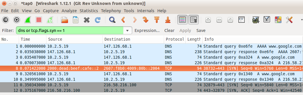
We see two DNS queries, AAAA and A, in packets 1-4, followed by the first attempt (highlighted in orange) at T=0.071 to negotiate a TCP connection via IPv6 by sending a TCP SYN packet (12.3 TCP Connection Establishment) to the google.com IPv6 address 2607:f8b0:4009:80b::200e. Only 250 ms later, at T=0.321, we see a second DNS A-query (IPv4), followed by an ultimately successful connection attempt using IPv4 starting at T=0.350. This particular version of Firefox, in other words, has implemented the Happy Eyeballs dual-stack mechanism.
Now we try the connection using the previously mentioned OpenSSH application, using -p 80 to connect to port 80. (This example was generated somewhat later; DNS now returns 2607:f8b0:4009:807::1004 as google.com’s IPv6 address.)
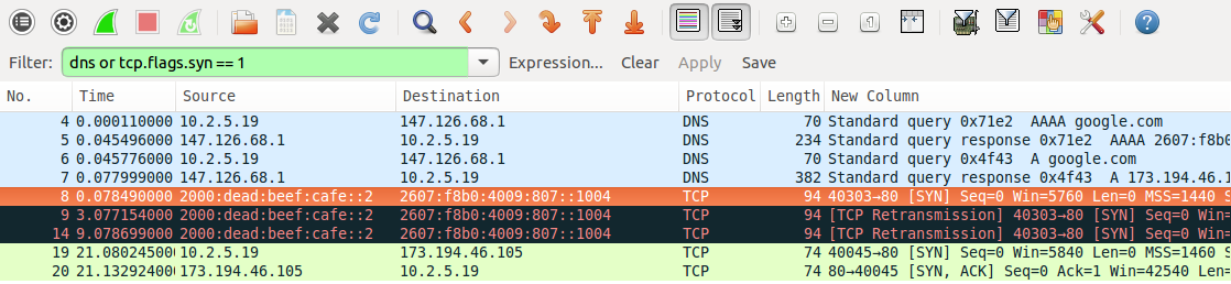
We see two DNS queries, AAAA and A, in packets numbered 4 and 6 (pale blue); these are made by the client from its IPv4 address 10.2.5.19. Half a millisecond after the A query returns (packet 7), the client sends a TCP SYN packet to google.com’s IPv6 address; this packet is highlighted in orange. This SYN packet is retransmitted 3 seconds and then 9 seconds later (in black), to no avail. After 21 seconds, the client gives up on IPv6 and attempts to connect to google.com at its IPv4 address, 173.194.46.105; this connection (in green) is successful. The long delay shows that Happy Eyeballs was not implemented by OpenSSH, which its source code confirms.
(The host initiating the connections here was running Ubuntu 10.04 LTS, from 2010. The ultimately failing TCP connection gives up after three tries over only 21 seconds; newer systems make more tries and take much longer before they abandon a connection attempt.)
8.12 IPv6 Examples Without a Router¶
In this section we present a few IPv6 experiments that can be done without an IPv6 connection and without even an IPv6 router. Without a router, we cannot use SLAAC or DHCPv6. We will instead use link-local addresses, which require the specification of the interface along with the address, and manually configured unique-local (8.3 Network Prefixes) addresses. One practical problem with link-local addresses is that application documentation describing how to include a specification of the interface is sometimes sparse.
8.12.1 ping6¶
The IPv6 analogue of the familiar ping command, used to send ICMPv6 Echo Requests, is ping6 on Linux and Mac systems and ping -6 on Windows. The ping6 command supports an option to specify the interface; eg -I eth0; as noted above, this is mandatory when sending to link-local addresses. Here are a few ping6 examples:
ping6 ::1: This pings the host’s loopback address; it should always work.
ping6 -I eth0 ff02::1: This pings the all-nodes multicast group on interface eth0. Here are two of the answers received:
- 64 bytes from fe80::3e97:eff:fe2c:2beb (this is the host I am pinging from)
- 64 bytes from fe80::2a0:ccff:fe24:b0e4 (a second Linux host)
Answers were also received from a Windows machine and an Android phone. A VoIP phone – on the same subnet but supporting IPv4 only – remained mute, despite VoIP’s difficulties with IPv4 NAT that would be avoided with IPv6. In lieu of the interface option -I eth0, the “zone-identifier” syntax ping6 ff02::1%eth0 also usually works; see the following section.
ping6 -I eth0 fe80::2a0:ccff:fe24:b0e4: This pings the link-local address of the second Linux host answering the previous query; again, the %eth0 syntax should also work. The destination interface identifier here uses the now-deprecated EUI-64 format; note the “ff:fe” in the middle. Also note the flipped seventh bit of the two bytes 02a0; the destination has Ethernet address 00:a0:cc:24:b0:e4.
8.12.2 TCP connections using link-local addresses¶
The next experiment is to create a TCP connection. Some commands, like ping6 above, may provide for a way of specifying the interface as a command-line option. Failing that, RFC 4007 defines the concept of a zone identifier that is appended to the IPv6 address, separated from it by a “%” character, to specify the link involved. On Linux systems the zone identifier is most often the interface name, eg eth0 or ppp1. Numeric zone identifiers are also used, in which case it represents the number of the particular interface in some designated list and can be called the zone index. On Windows systems the zone index for an interface can often be inferred from the output of the ipconfig command, which should include it with each link-local address. The use of zone identifiers is often restricted to literal (numeric) IPv6 addresses, perhaps because there is little demand for symbolic link-local addresses.
The following link-local address with zone identifier creates an ssh connection to the second Linux host in the example of the preceding section:
ssh fe80::2a0:ccff:fe24:b0e4%eth0
That the ssh service is listening for IPv6 connections can be verified on that host by netstat -a | grep -i tcp6. That the ssh connection actually used IPv6 can be verified by, say, use of a network sniffer like WireShark (for which the filter expression ipv6 or ip.version == 6 is useful). If the connection fails, but ssh works for IPv4 connections and shows as listening in the tcp6 list from the netstat command, a firewall-blocked port is a likely suspect.
8.12.3 Manual address configuration¶
The use of manually configured addresses is also possible, for either global or unique-local (ie not connected to the Internet) addresses. However, without a router there can be no Prefix Discovery, 8.6.2 Prefix Discovery, and this may create subtle differences.
The first step is to pick a suitable prefix; in the example below we use the unique-local prefix fd37:beef:cafe::/64 (though this particular prefix does not meet the randomness rules for unique-local prefixes). We could also use a globally routable prefix, but here we do not want to mislead any hosts about reachability.
Without a router as a source of Router Advertisements, we need some way to specify both the prefix and the prefix length; the latter can be thought of as corresponding to the IPv4 subnet mask. One might be forgiven for imagining that the default prefix length would be /64, given that this is the only prefix length generally allowed (8.3 Network Prefixes), but this is often not the case. In the commands below, the prefix length is included at the end as the /64. This usage is just slightly peculiar, in that in the IPv4 world the slash notation is most often used only with true prefixes, with all bits zero beyond the slash length. (The Linux ip command also uses the slash notation in the sense here, to specify an IPv4 subnet mask, eg 10.2.5.37/24. The ifconfig and Windows netsh commands specify the IPv4 subnet mask the traditional way, eg 255.255.255.0.)
Hosts will usually assume that a prefix configured this way with a length represents an on-link prefix, meaning that neighbors sharing the prefix are reachable directly via the LAN.
We can now assign the low-order 64 bits manually. On Linux this is done with:
- host1:
ip -6 address add fd37:beef:cafe::1/64 dev eth0 - host2:
ip -6 address add fd37:beef:cafe::2/64 dev eth0
Macintosh systems can be configured similarly except the name of the interface is probably en0 rather than eth0. On Windows systems, a typical IPv6-address-configuration command is
netsh interface ipv6 add address "Local Area Connection" fd37:beef:cafe::1/64
Now on host1 the command
ssh fd37:beef:cafe::2
should create an ssh connection to host2, again assuming ssh on host2 is listening for IPv6 connections. Because the addresses here are not link-local, /etc/host entries may be created for them to simplify entry.
Assigning IPv6 addresses manually like this is not recommended, except for experiments.
On a LAN not connected to the Internet and therefore with no actual routing, it is nonetheless possible to start up a Router Advertisement agent (8.6.1 Router Discovery), such as radvd, with a manually configured /64 prefix. The RA agent will include this prefix in its advertisements, and reasonably modern hosts will then construct full addresses for themselves from this prefix using SLAAC. IPv6 can then be used within the LAN. If this is done, the RA agent should also be configured to announce only a meaningless route, such as ::/128, or else nodes may falsely believe the RA agent is providing full Internet connectivity.
8.13 IPv6 Connectivity via Tunneling¶
The best option for IPv6 connectivity is native support by one’s ISP. In such a situation one’s router should be sending out Router Advertisement messages, and from these all the hosts should discover how to reach the IPv6 Internet.
If native IPv6 support is not forthcoming, however, a short-term option is to connect to the IPv6 world using packet tunneling (less often, some other VPN mechanism is used). RFC 4213 outlines the common 6in4 strategy of simply attaching an IPv4 header to the front of the IPv6 packet; it is very similar to the IPv4-in-IPv4 encapsulation of 7.13.1 IP-in-IP Encapsulation.
There are several available providers for this service; they can be found by searching for “IPv6 tunnel broker”. Some tunnel brokers provide this service at no charge.
The basic idea behind 6in4 tunneling is that the tunnel broker allocates you a /64 prefix out of its own address block, and agrees to create an IPv4 tunnel to you using 6in4 encapsulation. All your IPv6 traffic from the Internet is routed by the tunnel broker to you via this tunnel; similarly, IPv6 packets from your site reach the outside world using this same tunnel. The tunnel, in other words, is your link to an IPv6 router.
Generally speaking, the MTU of the tunnel must be at least 20 bytes less than the MTU of the physical interface, to allow space for the header. At the near end this requires a local configuration change; tunnel brokers often provide a way for users to set the MTU at the far end. Practical MTU values vary from a mandatory IPv6 minimum of 1280 to the Ethernet maximum of 1500−20 = 1480.
Setting up the tunnel does not involve creating a stateful connection. All that happens is that the tunnel client (ie your endpoint) and the broker record each other’s IPv4 addresses, and agree to accept encapsulated IPv6 packets from one another provided these two endpoint addresses are used as source and destination. The tunnel at the client end is represented by an appropriate “virtual network interface”, eg sit0 or gif0 or IP6Tunnel. Tunnel providers generally supply the basic commands necessary to get the tunnel interface configured and the MTU set.
Once the tunnel is created, the tunnel interface at the client end must be assigned an IPv6 address and then a (default) route. We will assume that the /64 prefix for the broker-to-client link is 2001:470:0:10::/64, with the broker at 2001:470:0:10::1 and with the client to be assigned the address 2001:470:0:10::2. The address and route are set up on the client with the following commands (Linux/Mac/Windows respectively; interface names may vary, and some commands assume the interface represents a point-to-point link):
ip addr add 2001:470:0:10::2/64 dev sit1
ip route add ::/0 dev sit1

ifconfig gif0 inet6 2001:470:0:10::2 2001:470:0:10::1 prefixlen 128
route -n add -inet6 default 2001:470:0:10::1

netsh interface ipv6 add address IP6Tunnel 2001:470:0:10::2
netsh interface ipv6 add route ::/0 IP6Tunnel 2001:470:0:10::1
At this point the tunnel client should have full IPv6 connectivity!
To verify this, one can use ping6, or visit IPv6-only versions of websites (eg intronetworks6.cs.luc.edu), or visit IPv6-identifying sites such as IsMyIPv6Working.com. Alternatively, one can often install a browser plugin to at least make visible whether IPv6 is used. Finally, one can use netcat with the -6 option to force IPv6 use, following the HTTP example in 12.6.2 netcat again.
There is one more potential issue. If the tunnel client is behind an IPv4 NAT router, that router must deliver arriving encapsulated 6in4 packets correctly. This can sometimes be a problem; encapsulated 6in4 packets are at some remove from the TCP and UDP traffic that the usual consumer-grade NAT router is primarily designed to handle. Careful study of the router forwarding settings may help, but sometimes the only fix is a newer router. A problem is particularly likely if two different inside clients attempt to set up tunnels simultaneously; see 7.13.1 IP-in-IP Encapsulation.
8.13.1 IPv6 firewalls¶
It is strongly recommended that an IPv6 host block new inbound connections over its IPv6 interface (eg the tunnel interface), much as an IPv4 NAT router would do. Exceptions may be added as necessary for essential services (such as ICMPv6). Using the linux ip6tables firewall command, with IPv6-tunneled interface sit1, this might be done with the following:
ip6tables --append INPUT --in-interface sit1 --protocol icmpv6 --jump ACCEPT
ip6tables --append INPUT --in-interface sit1 --match conntrack --ctstate ESTABLISHED,RELATED --jump ACCEPT
ip6tables --append INPUT --in-interface sit1 --jump DROP
At this point the firewall should be tested by attempting to access inside hosts from the outside. At a minimum, ping6 from the outside to any global IPv6 address of any inside host should fail if the ICMPv6 exception above is removed (and should succeed if the ICMPv6 exception is restored). This can be checked by using any of several websites that send pings on request; such sites can be found by searching for “online ipv6 ping”. There are also a few sites that will run a remote IPv6 TCP port scan; try searching for “online ipv6 port scan”. See also exercise 7.0.
8.13.2 Setting up a router¶
The next step, if desired, is to set up the tunnel endpoint as a router, so other hosts at the client site can also enjoy IPv6 connectivity. For this we need a second /64 prefix; we will assume this is 2001:470:0:20::/64 (note this is not an “adjacent” /64; the two /64 prefixes cannot be merged into a /63). Let R be the tunnel endpoint, with eth0 its LAN interface, and let A be another host on the LAN.
We will use the linux radvd package as our Router Advertisement agent (8.6.1 Router Discovery). In the radvd.conf file, we need to say that we want the LAN prefix 2001:470:0:20::/64 advertised as on-link over interface eth0:
interface eth0 {
       ...
       prefix 2001:470:0:20::/64
       {
               AdvOnLink on;         # advertise this prefix as on-link
               AdvAutonomous on;     # allows SLAAC with this prefix
       };
};
If radvd is now started, other LAN hosts (eg A) will automatically get the prefix (and thus a full SLAAC address). Radvd will automatically share R’s default route (::/0), taking it not from the configuration file but from R’s routing table. (It may still be necessary to manually configure the IPv6 address of R’s eth0 interface, eg as 2001:470:0:20::1.)
On the author’s version of host A, the IPv6 route is now (with some irrelevant attributes not shown)
default via fe80::2a0:ccff:fe24:b0e4 dev eth0
That is, host A routes to R via the latter’s link-local address, always guaranteed on-link, rather than via the subnet address.
If radvd or its equivalent is not available, the manual approach is to assign R and A each a /64 address:
On host R:ip -6 address add 2001:470:0:20::1/64 dev eth0On host A:ip -6 address add 2001:470:0:20::2/64 dev eth0
Because of the “/64” here (8.12.3 Manual address configuration), R and A understand that they can reach each other via the LAN, and do so. Host A also needs to be told of the default route via R:
On host A:ip -6 route add ::/0 via 2001:470:0:10::1 dev eth0
Here we use the subnet address of R, but we could have used R’s link-local address as well.
It is likely that A’s eth0 will also need its MTU configured, so that it matches that of R’s virtual tunnel interface (which, recall, should be at least 20 bytes less than the MTU of R’s physical outbound interface).
8.13.2.1 A second router¶
Now let us add a second router R2, as in the diagram below. The R──R2 link is via a separate Ethernet LAN, not a point-to-point link. The LAN with A is, as above, subnet 2001:470:0:20::/64.

In this case, it is R2 that needs to run the Router Advertisement agent (eg radvd). If this were an IPv4 network, the interfaces eth0 and eth1 on the R──R2 link would need IPv4 addresses from some new subnet (though the use of private addresses is an option). We can’t use unnumbered interfaces (7.12 Unnumbered Interfaces), because the R──R2 connection is not a point-to-point link.
But with IPv6, we can configure the R──R2 routing to use only link-local addresses. Let us assume for mnemonic convenience these are as follows:
R’s eth0:fe80::ba5e:ba11R2’s eth1:fe80::dead:beef
R2’s forwarding table will have a default route with next_hop fe80::ba5e:ba11 (R). Similarly, R’s forwarding table will have an entry for destination subnet 2001:470:0:20::/64 with next_hop fe80::dead:beef (R2). Neither eth0 nor eth1 needs any other IPv6 address.
R2’s eth2 interface will likely need a global IPv6 address, eg 2001:470:0:20::1 again. Otherwise R2 may not be able to determine that its eth2 interface is in fact connected to the 2001:470:0:20::/64 subnet.
One advantage of not giving eth0 or eth1 global addresses is that it is then impossible for an outside attacker to reach these interfaces directly. It also saves on subnets, although one hopes with IPv6 those are not in short supply. All routers at a site are likely to need, for management purposes, an IP address reachable throughout the site, but this does not have to be globally visible.
8.14 IPv6-to-IPv4 Connectivity¶
What happens if you switch to IPv6 completely, perhaps because your ISP (or phone provider) has run out of IPv4 addresses? Some of the time – hopefully more and more of the time – you will only need to talk to IPv6 servers. For example, the DNS names facebook.com and google.com each correspond to an IPv4 address, but also to an IPv6 address (above). But what do you do if you want to reach an IPv4-only server? Such servers are expected to continue operating for a long time to come. It is necesary to have some sort of centralized IPv6-to-IPv4 translator.
An early strategy was NAT-PT (RFC 2766). The translator was assigned a /96 prefix. The IPv6 host would append to this prefix the 32-bit IPv4 address of the destination, and use the resulting address to contact the IPv4 destination. Packets sent to this address would be delivered via IPv6 to the translator, which would translate the IPv6 header into IPv4 and then send the translated packet on to the IPv4 destination. As in IPv4 NAT (7.7 Network Address Translation), the reverse translation will typically involve TCP port numbers to resolve ambiguities. This approach requires the IPv6 host to be aware of the translator, and is limited to TCP and UDP (because of the use of port numbers). Due to these and several other limitations, NAT-PT was formally deprecated in RFC 4966.
The replacement protocol is NAT64, documented in RFC 6146. This is also based on address translation, and, as such, cannot allow connections initiated from IPv4 hosts to IPv6 hosts. It is, however, transparent to both the IPv6 and IPv4 hosts involved, and is not restricted to TCP (though only TCP, UDP and ICMP are supported by RFC 6146). It uses a special DNS variant, DNS64 (RFC 6147), as a companion protocol.
To use NAT64, an IPv6 client sends out its ordinary DNS query to find the addresses of the destination server. The DNS resolver (7.8 DNS) receiving the request must use DNS64. If the destination has only an IPv4 address, then the DNS resolver will return to the IPv6 client (as an AAAA record) a synthetic IPv6 address consisting of a prefix and the embedded IPv4 address of the server, much as in NAT-PT above (though multiple prefix-length options exist; see RFC 6052). The prefix belongs to the actual NAT64 translator; any packet addressed to an IPv6 address starting with the prefix will be delivered to the translator. There is no relationship between the NAT64 translator and the DNS64 resolver beyond the fact that the former’s prefix is configured into the latter.
The IPv6 client now uses this synthetic IPv6 address to contact the IPv4 server. Its packets will be routed to the NAT64 translator itself, by virtue of the prefix, much as in NAT-PT. Upon receiving the first packet from the IPv6 client, the NAT64 translator will assign one of its IPv4 addresses to the new connection. As IPv4 addresses are in short supply, this pool of available IPv4 addresses may be small, so NAT64 allows one IPv4 address to be used by many IPv6 clients. To this end, the NAT64 translator will also (for TCP and UDP) establish a port mapping between the incoming IPv6 source port and a port number allocated by the NAT64 to ensure that traffic is uniquely reversable. As with IPv4 NAT, if two IPv6 clients try to contact the same IPv4 server using the same source ports, and are assigned the same NAT64 IPv4 address, then one of the clients will have its port number changed.
If an ICMP query is being sent, the Query Identifier is used in lieu of port numbers. To extend NAT64 to new protocols, an appropriate analog of port numbers must be identified, to allow demultiplexing of multiple connections sharing a single IPv4 address.
After the translation is set up, by creating appropriate table entries, the translated packet is sent on to the IPv4 server address that was embedded in the synthetic IPv6 address. The source address will be the assigned IPv4 address of the translator, and the source port will have been rewritten in accordance with the new port mapping. At this point packets can flow freely between the original IPv6 client and its IPv4 destination, with neither endpoint being aware of the translation (unless the IPv6 client carefully inspects the synthetic address it receives via DNS64). A timer within the NAT64 translator will delete the association between the IPv6 and IPv4 addresses if the connection is not used for a while.
As an example, suppose the IPv6 client has address 2000:1234::abba, and is trying to reach intronetworks4.cs.luc.edu at TCP port 80. It contacts its DNS server, which finds no AAAA record but IPv4 address 162.216.18.28 (in hex, a2d8:121c). It takes the prefix for its NAT64 translator, which we will assume is 2000:cafe::, and returns the synthetic address 2000:cafe::a2d8:121c.

The IPv6 client now tries to connect to 2000:cafe::a2d8:121c, using source port 4000. The first packet arrives at the NAT64 translator, which assigns the connection the outbound IPv4 address of 200.0.0.1, and reassigns the source port on the IPv4 side to 4002. The new IPv4 packet is sent on to 162.216.18.28. The reply from intronetworks4.cs.luc.edu comes back, to (200.0.0.1,4002). The NAT64 translator looks this up and finds that this corresponds to (2000:1234::abba,4000), and forwards it back to the original IPv6 client.
8.15 Epilog¶
IPv4 has run out of large address blocks, as of 2011. IPv6 has reached a mature level of development. Most common operating systems provide excellent IPv6 support.
Yet conversion has been slow. Many ISPs still provide limited (to nonexistent) support, and inexpensive IPv6 firewalls to replace the ubiquitous consumer-grade NAT routers are just beginning to appear. Time will tell how all this evolves. However, while IPv6 has now been around for twenty years, top-level IPv4 address blocks disappeared much more recently. It is quite possible that this will prove to be just the catalyst IPv6 needs.
8.16 Exercises¶
Exercises are given fractional (floating point) numbers, to allow for interpolation of new exercises.
1.0. Each IPv6 address is associated with a specific solicited-node multicast address.
(a). Explain why, on a typical Ethernet, if the original IPv6 host address was obtained via SLAAC then the LAN multicast group corresponding to the host’s solicited-node multicast addresses is likely to be small, in many cases consisting of one host only. (Packet delivery to small LAN multicast groups can be much more efficient than delivery to large multicast groups.)
(b). What steps might a DHCPv6 server take to ensure that, for the IPv6 addresses it hands out, the LAN multicast groups corresponding to the host addresses’ solicited-node multicast addresses will be small?
2.0. If an attacker sends a large number of probe packets via IPv4, you can block them by blocking the attacker’s IP address. Now suppose the attacker uses IPv6 to launch the probes; for each probe, the attacker changes the low-order 64 bits of the address. Can these probes be blocked efficiently? If so, what do you have to block? Might you also be blocking other users?
3.0. Suppose someone tried to implement ping6 so that, if the address was a link-local address and no interface was specified, the ICMPv6 Echo Request was sent out all non-loopback interfaces. Could the end result be different than conventional ping6 with the correct interface supplied? If so, how likely is this?
4.0. Create an IPv6 ssh connection as in 8.12 IPv6 Examples Without a Router. Examine the connection’s packets using WireShark or the equivalent. Does the TCP handshake (12.3 TCP Connection Establishment) look any different over IPv6?
5.0. Create an IPv6 ssh connection using manually configured addresses as in 8.12.3 Manual address configuration. Again use WireShark or the equivalent to monitor the connection. Is DAD (8.7.1 Duplicate Address Detection) used?
6.0. An IPv6 fixed-header is 40 bytes. Taking this as the minimum packet size, how long will it take to send 1015 hosts (one quadrillion) probe packets to a site, if the bandwidth is 1 Gbps?
7.0. Suppose host A gets its IPv6 traffic through tunnel provider H, as in 8.13 IPv6 Connectivity via Tunneling. To improve security, A blocks all packets that are not part of connections it has initiated, and makes no exception for ICMPv6 traffic. H is correctly configured to know the MTU of the A–H link. For (a) and (b), this MTU is 1280, the minimum allowed for IPv6. Much of the Internet, however, allows larger MTU values.
A ─── H ─── Internet ─── B
(a). If A attempts to send a larger-than-1280-byte IPv6 packet to remote host B, will A be informed of the resultant failure? Why or why not?
(b). Suppose B attempts to send a larger-than-1280-byte IPv6 packet to A. Will B receive an ICMPv6 Packet Too Big message? Why or why not?
(c). Now suppose the MTU of the A–H link is raised to 1400 bytes. Outline a scenario in which A sends a packet of size greater than 1280 bytes to remote host B, the packet is too big to make it all the way to B, and yet A receives no notification of this.